 |
|

 STEP 1 STEP 1
Connect the Y wire to the Y terminal on the thermostat.
This connects to the Cooler compressor.
 STEP 2 STEP 2
Connect the RH or RC wire to the RH terminal on the thermostat.
This connects the heater control line to the thermostat.
 STEP 3 STEP 3
Connect the W wire to the W terminal on the thermostat.
This connects to the heater control line.
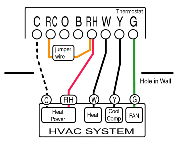 STEP 4 STEP 4
Connect the G wire to the G terminal on the Thermostat.
This connects to the Fan.
Your HVAC system is now conected to the thermostat.
 STEP 5 STEP 5
If you have the optional C-wire connect it now, this will supply aux power to your thermostat and eliminate the need to replace batteries.
Note: If the C-wire is not present the thermostat will function correctly. Be advised w/o the C-wire you must replace your thermostat's batteries regularly. If you would like to have the no battery replacement feature, you can install a C-wire from your system. See Installing A C-Wire.
You should now follow the remaining steps to verify you have correctly installed the unit.
STEP 6
You can now turn the power back on to your system.
Check HEAT mode by performing the following tasks:
- Set the mode switch to HEAT.
- Set the fan switch AUTO.
- Set the TEMP setting to its maximum. Allow the system 5 min to respond.
- Verify that heat is blowing from the system.
STEP 7
Check COOL mode by performing the following tasks:
- Set the TEMP setting to its minimum.
- Allow the system 5 min to respond.
- Verify that cool air is blowing from the system.
STEP 8
Check the FAN by performing the following tasks:
(Only if you connected the G wire for the fan relay)
- Switch the FAN switch to the ON position.
- Verify that air is blowing from the system.
- Return to AUTO position for normal operation.
STEP 9
Your system should now be operational.
If your system is still not working correctly, please check all the steps once again.
We can start to check if there is problem in your system by following the Trouble Shooting procedure.
After you have rechecked your steps for installation, and trouble shot your system, you can contact via email.
Installation Complete!
Your system should now be operational.
If your system is still not working correctly, please check all the steps once again.
We can start to check if there is problem in your system by following the Trouble Shooting procedure.
After you have rechecked your steps for installation, and trouble shot your system, you can contact via email.
|
 |
|
|
|
|